Description
Belt Grinder, 2 x 72” Assembly Instructions
- Note the grinder is heavy, being 2 people to lift it out of the crate is required
- Assembly is not difficult, but there are photos below to help
- Tools required: Allen keys in 5, 6 and 9 mm and an adjustable wrench
These are the assembly instructions for this grinder: LINK
- Lift grinder out of crate after unscrewing the grinder body from the crate. This will require 2 people.
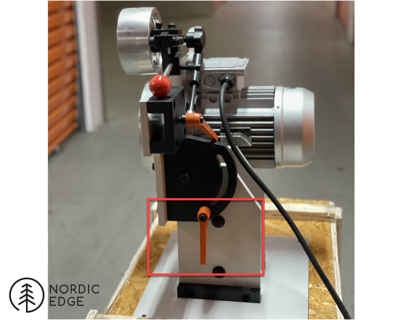
- Loosen bottom orange handle, tilt grinder up vertically, tighten orange handle
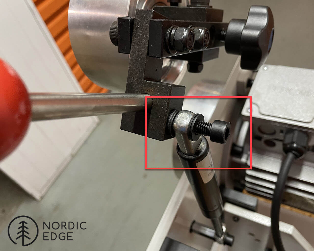
- Attach gas strut to bolt with washers, tighten with 6 mm allen key
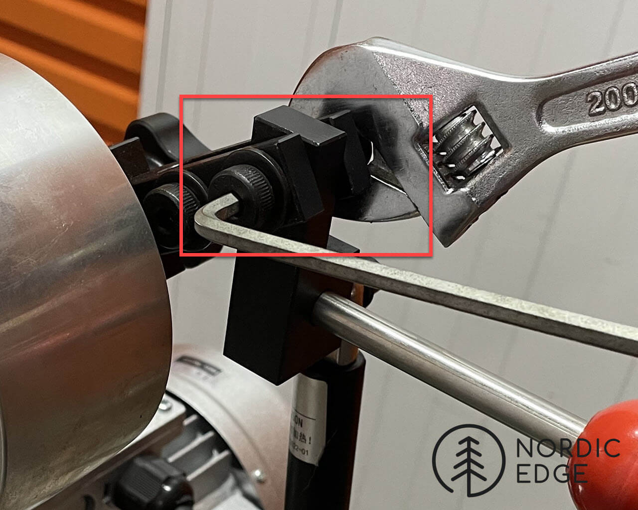
- Tighten bolts for arm holding gas strut with 5 mm allen key and an adjustable shifter
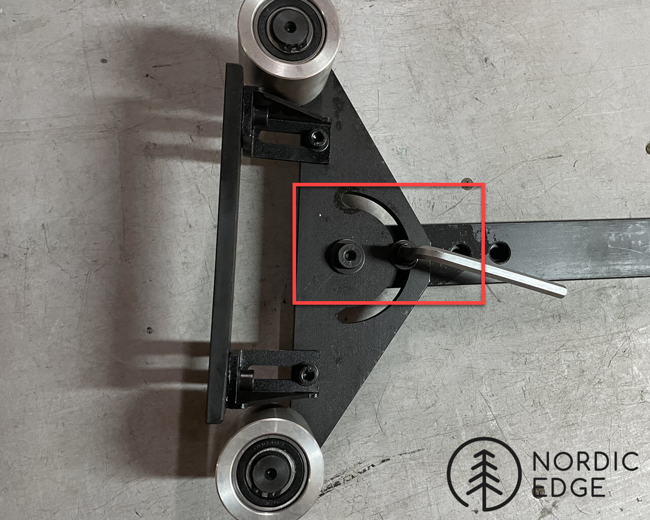
- Loosen bolt to swing platen up to 90 degrees, tighten bolt loosely with a 5 mm allen key. Best to not tighten this fully until assembled so you can make sure it is 90 degrees to the work rest.
- Insert platen tooling arm in holder, adjust orange handle and (possibly bolts on cover for tooling with an allen key) until the arm moves freely in and out with little play.
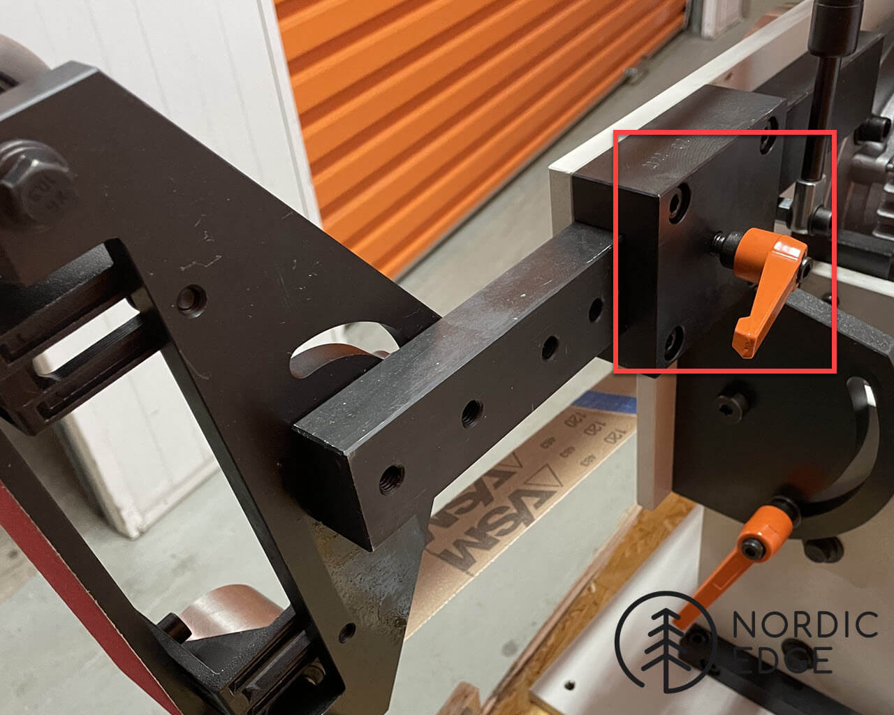
- Add an abrasive belt before aligning platen; Some prefer the platen inline with the outside of the wheels, others the platen slightly outside of the wheels to enable flattening long work pieces without risking hitting the wheels. The further out the platen is placed, the more friction and heat will be created.
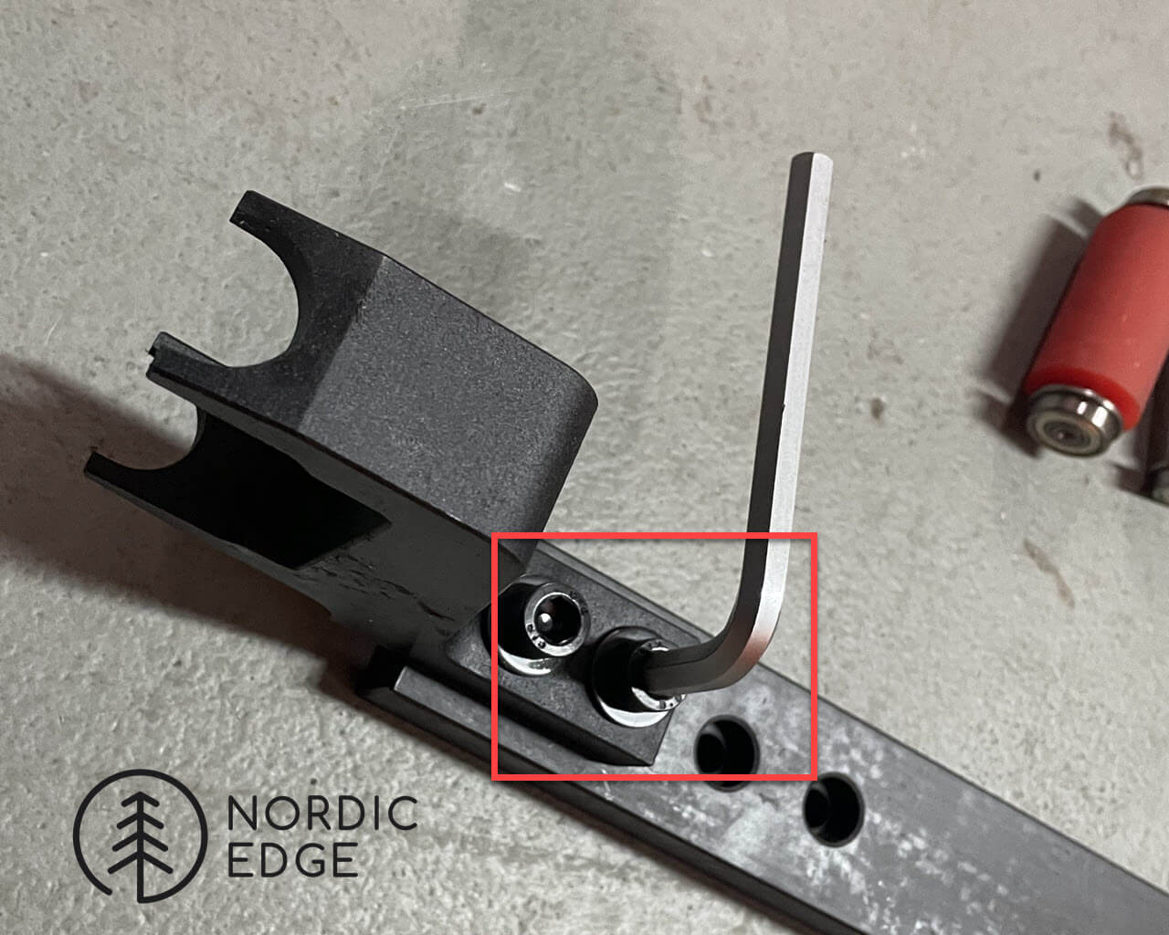
- To align the platen in and out, use an allen key on the 2 bolts within the red rectangles in the photo below.

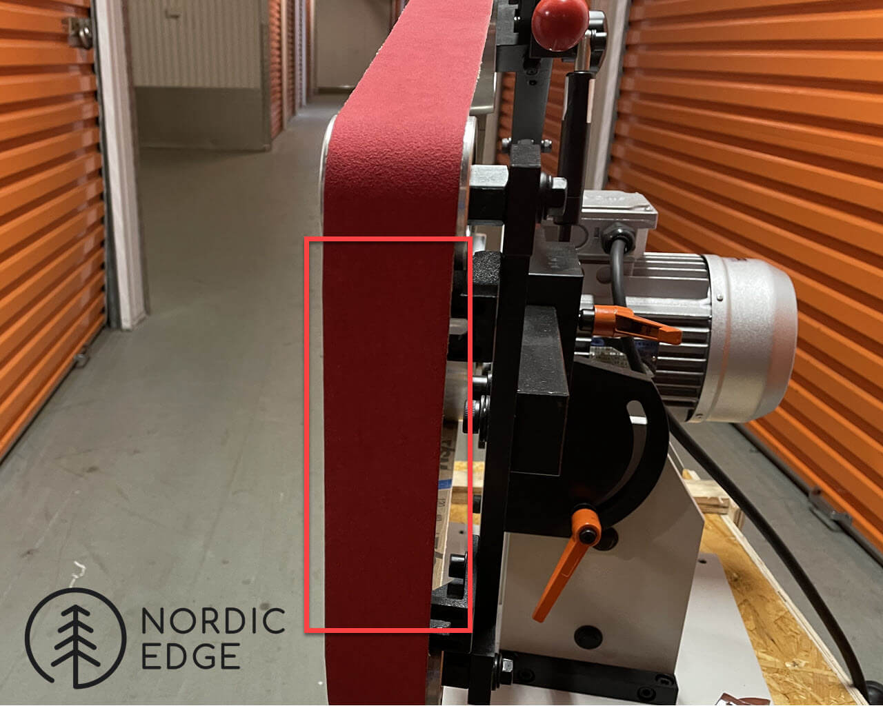
- The platen might also need to be centred on the belt; loosen the below bolts, move platen sideways until belt covers platen when standing in front on the abrasive belt, then tighten bolts again;

- Photo showing platen adjusted to be in the middle of the abrasive belt. In use belts will often sit to the right and left of centre, and this is adjusted every time a belt is changed using the tracking wheel. But for now, aim to place the platen in the centre of the belt. Spin the wheels by hand to set the belt before doing this step.
- Grinder is now assembled and can be used, there are are 3 more optional accessories:
Additional setup:
- Tool rest
- Large wheel (for hollow grinding, and faster stock removal)
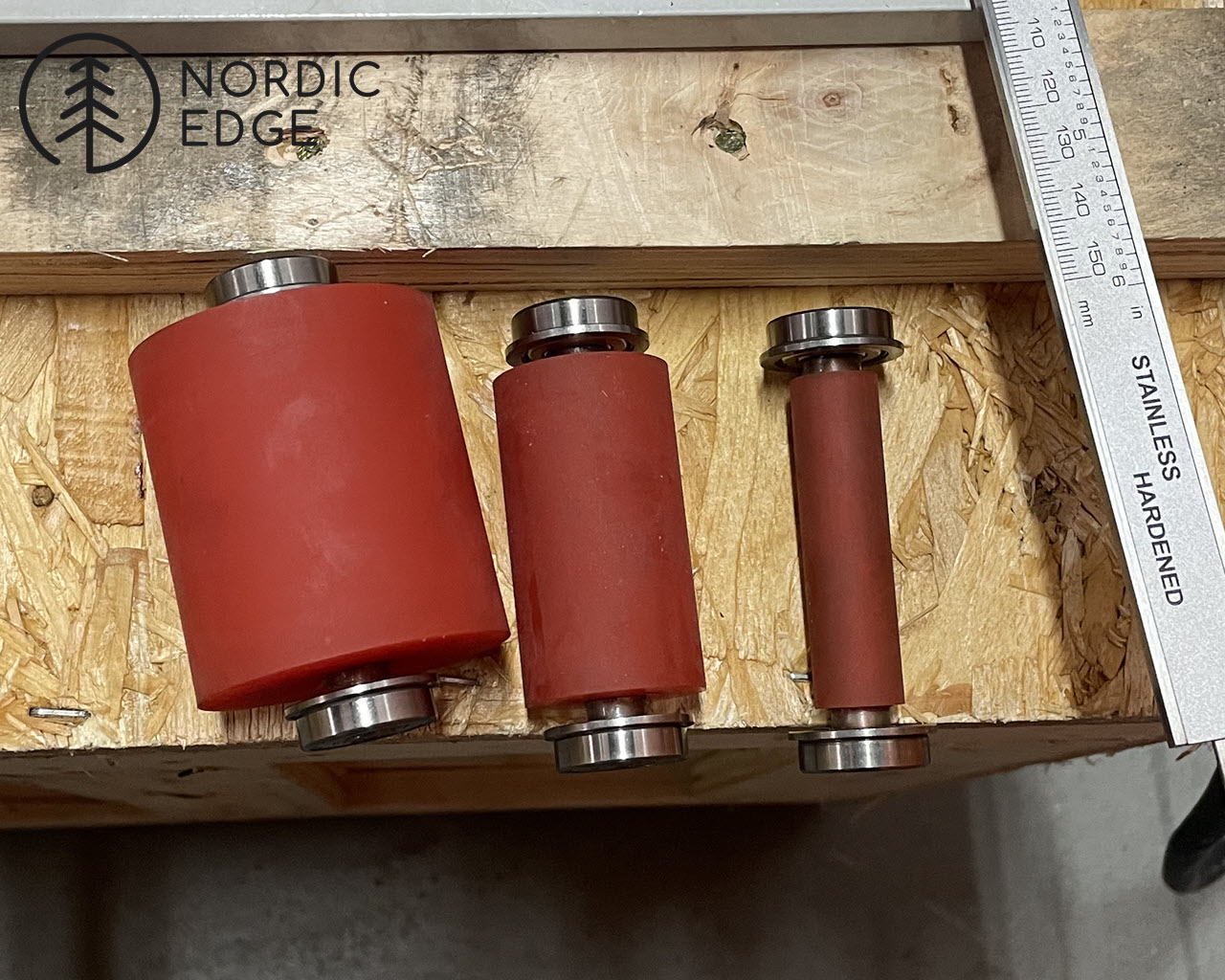
- Small wheel attachment and small wheels in 15, 30 and 50 mm diameter.
- Large wheel assembly: Attach the large wheel to it’s own tooling arm, and insert into tooling arm holder.
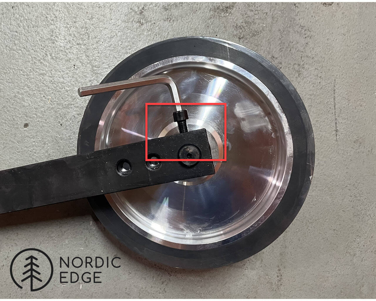
- Grinder with large wheel for fast material removal and hollow grinding;
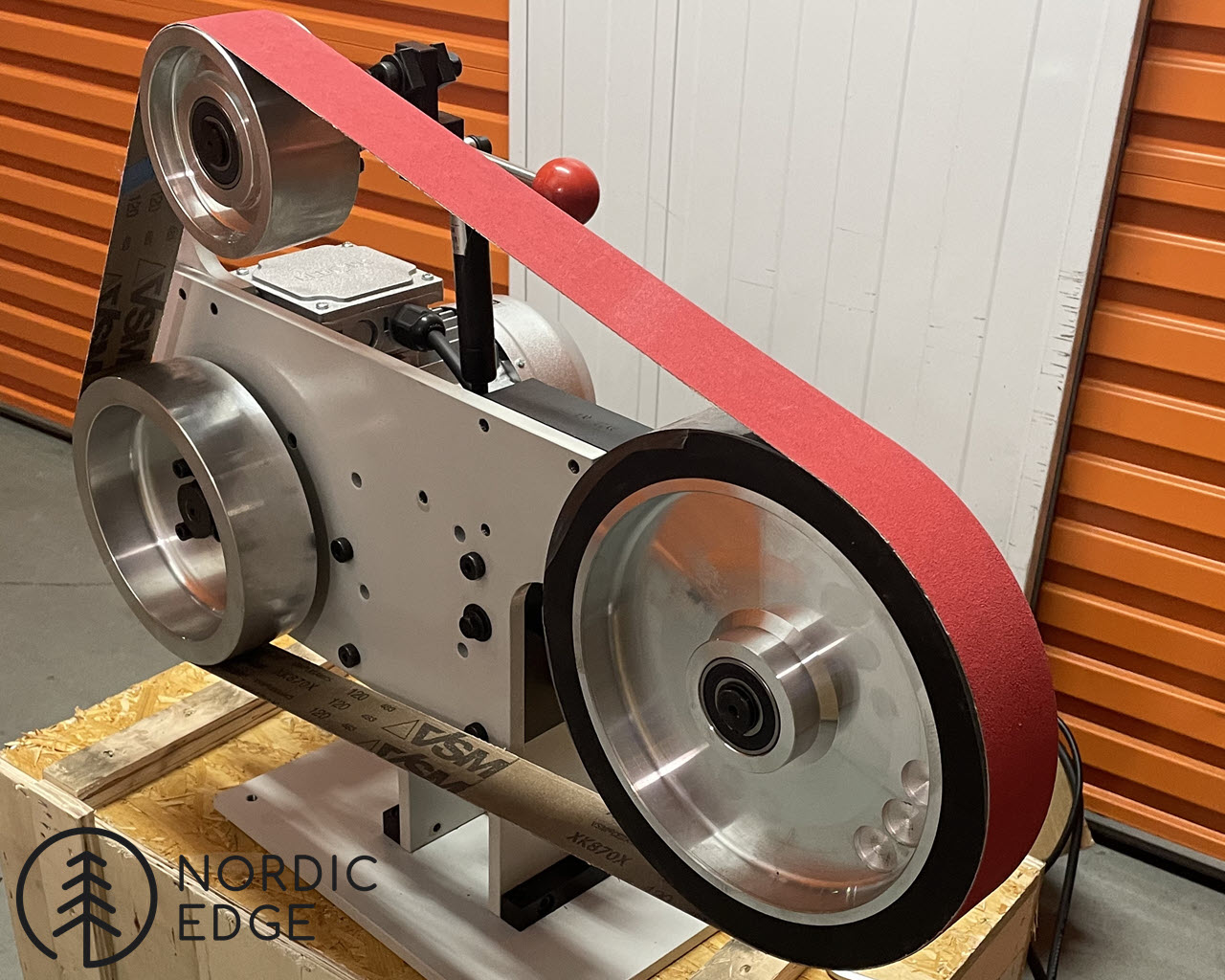
- Small wheel attachment: MUST BE USED AT LOW SPEED.
- Wheels are 15, 30 and 50 mm in diameter, the small wheel holder is attached to it’s own tooling arm, the arm inserted in the tooling arm holder before the wheel is loaded.
- NOTE that these must be run at low speed, they are for fine working rounding inside finger grooves etc and not for hard stock removal or high speed.
- To use the small wheels, always reduce speed before changing to the small wheel tooling arm, and be ready to adjust tracking as soon as the motor starts moving again.
- Use a 9 mm Allen key to attach the small wheel holder to it's tooling arm;

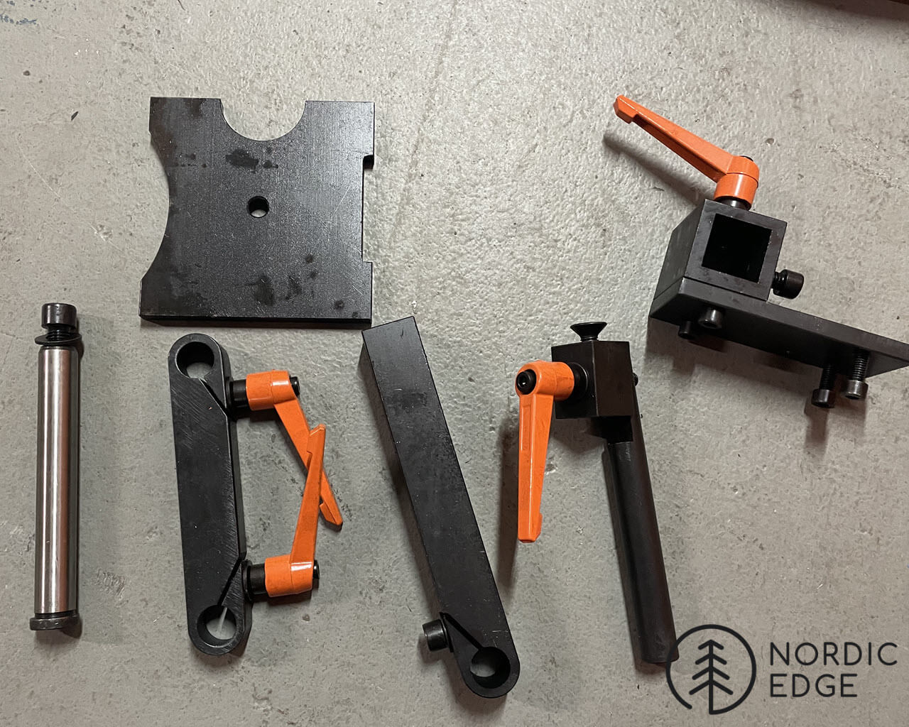
- Adjustable tool rest parts:
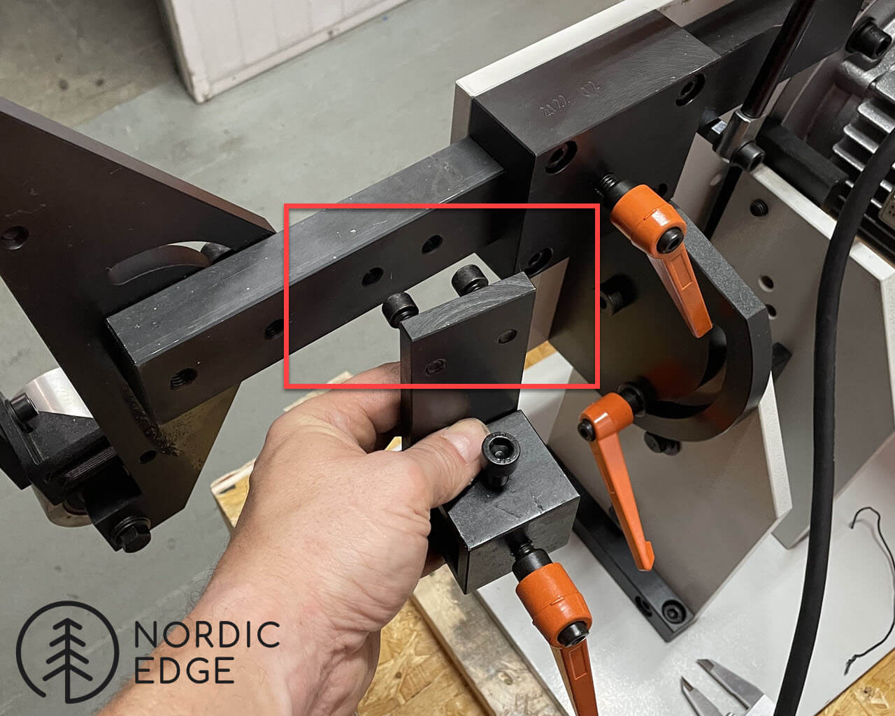
- Attach the tool rest holder to one of the tooling arms – usually this goes on the tooling arm for the platen and be moved between tooling arms as required.
- The bolts are threaded back in from the back of the tooling arm using a 6 mm Allen key.
- Insert the short tooling arm for the work rest table into the tool rest holder
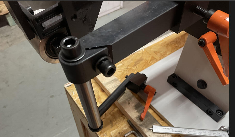
- Attach the work rest table on top of the part shown on the left. Note each side has a different profile for use against a wheel or flat platen. Use the side with a rectangular cut in it towards the flat platen, the abrasive belt and platen will fit into this cut-out.
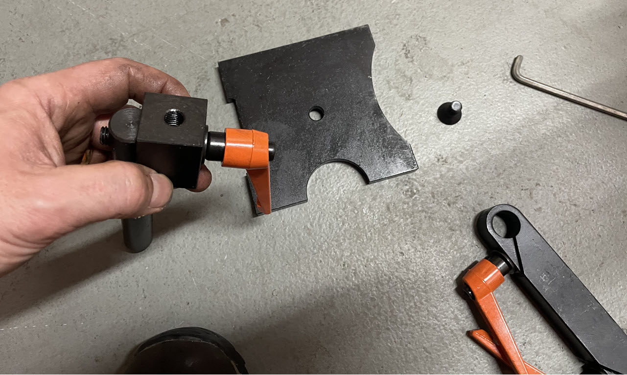
- Use the arm on the right side of the photo above to connect the 2 steel solid round bars. This completes the work rest assembly.
- Note the orange handles that are used to tighten the bolts, are spring loaded. You pull the handle straight off the bolt, move it, and lower it again. This way you can tighten further than the handle goes without lifting it.
- When the work rest is assembled, before starting to grind, make sure it is 90 degrees to the platen by placing a straight edge on the table and move it towards the platen. Adjust work rest as needed.
Operating the grinder:
- The VDF is for speed control, and is in a dust protected enclosure. Attach this away from the grinder to not be in direct line of sparks or dust coming off the grinder.
- To use the grinder, press the Green button on the VFD, this starts the grinder up.
- To stop the grinder, press the Red button on the VFD, this stops the power to the motor.
- The Up and Down speed buttons on the VFD are used to adjust the speed, and can be pressed while the grinder is powering up and down to set the speed.
- Speed recommendations :
- For rough grinding, up to 120 grits, full speed
- For ceramic belts, always use full speed as these belts can glaze over and dull if run slowly
- For alu oxide belts, there is no advance in running them at full speed, lower speed might give more control
- For higher grit belts (180+) it is often better to run them slower, the higher the grit, the slower the speed.
- Small wheels MUST BE RUN SLOWLY to not burn the ball bearings out
- The red ball on the right side of the grinder, is pressed down to change belts.
- Every time you change the belt, be ready to adjust the tracking when turning the grinder back on. Often every belt needs a slight adjustment of the tracking to be centered over the platen when standing in front of the belt.
- Belt tracking is the black bolt behind the red ball used to change belts.
- The work rest is usually used on the tooling arm for the flat platen, but can be changed over to the other tooling arms should this be needed.


