
Making an anvil stand with retractable wheels
Now this is a special anvil stand! Steve C from Black Rose Studio in Northern NSW was kind enough to share with us detailed plans for how he made this awesome anvil stand with retractable wheels. Check out his story here:
It was time to level up my anvil game.
I'd been learning on one of those tiny ubiquitous 10kg ones. If you're grinning wryly, you know what I mean... it had served me well but I'd reached its limit; too small a face, too thick a horn, soft steel hardy hole rounded out a bit, and not nearly enough mass to properly honour the forge gods with suitably sound blows.
Bjorn and the kind folk at NordicEdge rescued me there. Proper tools are an investment. I'd saved and the "Troy" had me at hello - good steel, good size, great refinements (thanks Troy Hageman/Nowra Knives!!), and all the helpful assistance to bring it to the doorstep without fuss.
Standing back and admiring its hefty shiny usefulness at delivery, the design cogs started turning...
My shed/shop is not large, and it's got to serve different functions at different times. There's a need for modularity. Keisha Wurth in a meet-the-maker post here was gifted some sage advice, "put everything on wheels..." it rings true for me in a big way. I couldn't plant my anvil in one spot. It needed wheels.
I take zero credit for the mechanics here, Jimmy Diresta via Youtube (https://youtu.be/vEJ2Gr5fjXc) has been kind enough to share his blow-by-blow creativity, along with the elegant lesson in physics that is this up and over locking lever. With imitation being the sincerest form of larceny, this monkey simply saw and did, with some small adjustments I thought appropriate. (N.B: he encourages other makers to give it a go in the video description, so no IP was harmed in the making of this...).
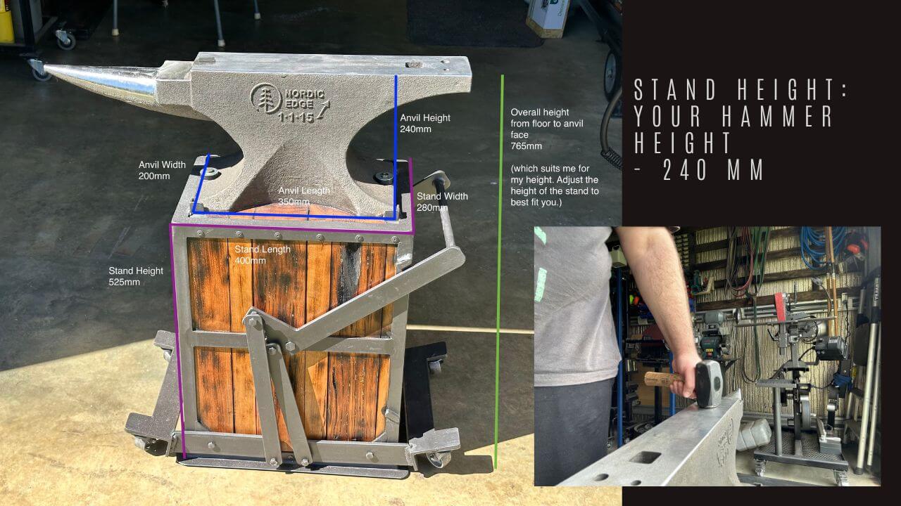
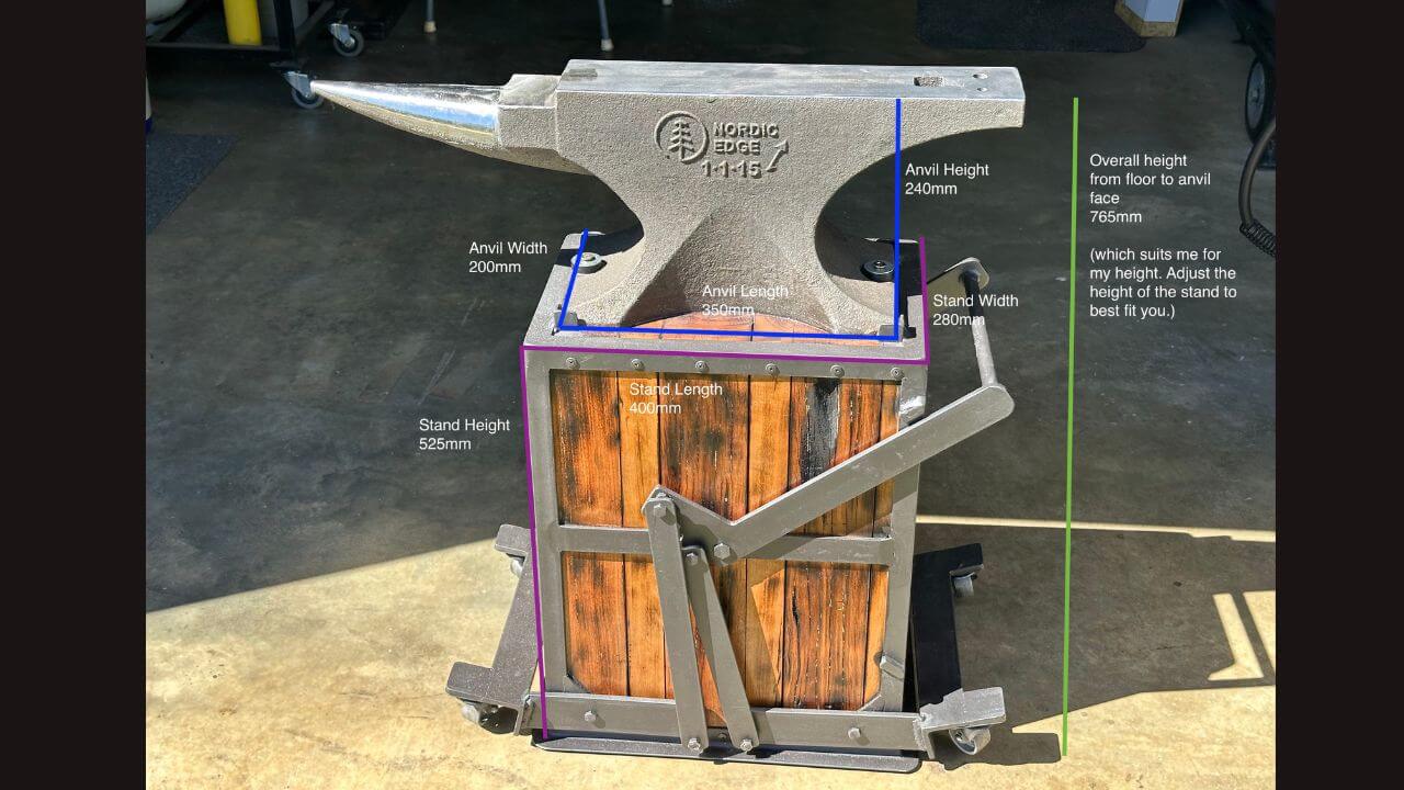
First up, overall height and working backwards. My comfortable-stance-slightly-bent-elbow-with-hammer-in-hand held flat against what would be the anvil face was give or take ~765mm from the floor. Figure this height out for YOUR dimensions - and start substracting. The anvil height is 240mm, which meant my stand needed to be 525mm.
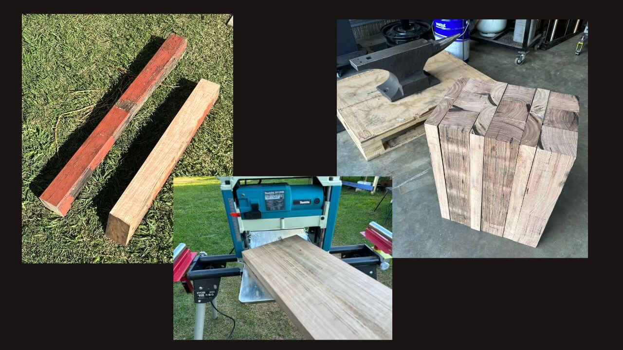
Being a make-do kinda creative, those old 90x90 hardwood deck supports squirrelled away behind the shed got dragged out and the noisy, lengthy and fairly laborious process of upcycling began. Planing off the paint, and coincidentally causing each stick to become flat, revealed some beautiful seasoned timber underneath.
A quick measure and section up (and realising I didn’t quite have enough for what was needed) meant another dive into the spares bin for a make up the difference plank and some Tetris worthy alternate stacking and gluing. Overall width and length ended up ~280mm x 400mm (x 525mm high!!), which was just enough to overhang the anvil base on all sides. I paid attention to sanding the top and bottom (mostly) flat - it doesn't rock at any rate.
Do I trust glue? Sure, to stick fingers together, or make your workpiece and the bench it’s drying on a single solid swear-worthy construction... definitely. It’s great. But alone as the sole connection being flogged repeatedly under a heavy anvil over time? Not so much..
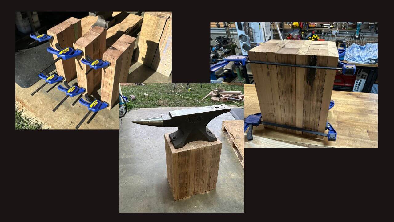
Wrapping the stand in steel too seemed a much better idea. I used 25mm angle. Cut & welded the top surround first, then surrounded the bottom, and joined top to bottom with uprights in each corner and screws placed strategically to marry the two mediums firmly. Side-Tip: sand the timber edges all around to clearance that inside fillet angle iron has, that keeps a firm & flush fit. You'll notice I also turned the base steel outwards. I wanted the whole bottom surface of the timber in contact with the ground rather than wrapping the steel underneath. That does a few things, it doesn't mess with my calculated height, it keeps steel from impacting concrete, and helps with resonance to dampen the anvil ringing.
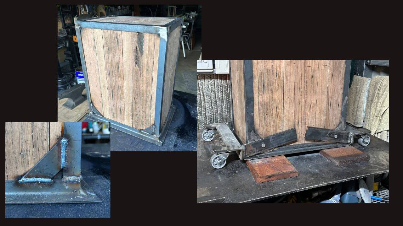
Jimmy screwed his stuff directly into timber. I prefer steel on steel when we're talking hinges and pivots. That invited a cross strap halfway up the stand, and some angle brackets at the base seemed appropriate (40x6mm flat bar), and offered spots to tap and thread - acting as solid pivot points that will hopefully wear less over time than straight into timber would. The main pivot on each side is an M12x75mm bolt, with it tapped centrally smack in the middle of the stand (the height of this can probably vary, maybe good to give yourself enough room though for the linkages to maintain a decent arc - them crossing over and uncrossing an imaginary perpendicular centre line is what makes this all work). All other hardware is M6 bolts of various length (I had a pack of 40mm and cut them to size as needed).
Being more a goal than a plan, there’s no absolute way to figure out the mechanism. It will vary depending on height, geometry and how far up you want to throw those wheels up. Before you gnash your teeth and wail though - re-watch Jimmy's video - and take notes. I started with raising the whole stand on some decking boards to give a decent clearance underneath of about 20mm with the wheels down. Next, fabricated the wheel sections with heavy angle and stick out extensions (for the dolley wheels to spin 360). This was sized to the width of the stand, and pivot arms put on... with the wheels in position on the table in the fully down position. My arms by necessity angled up so they had room to move when the mechanism throws and wheels come off the ground. Starting with this position and setup, the rest kinda worked itself out, without burdening me with an overabundance of schooling!
Switching gear then to the central pivot, I needed two main arms, one for each side (this mechanism is duplicated on both sides of the stand). Some hefty 40x6mm flat bar was used so it didn't flex, with an 80mm-ish tab welded like a hockey stick on the pivot end. 12mm hole drilled for the central pivot and the bolt head ground down thinner so it didn't stick out too much (leave enough to get a spanner on!!). These arms were cut long enough to stick out past the stand so we can weld a handle on and join the two arms (16mm round bar) with the added benefit of not dusting your knuckles with each throw of the lever. I subsequently put a hammer holder on that end, so my knuckles have no hope.
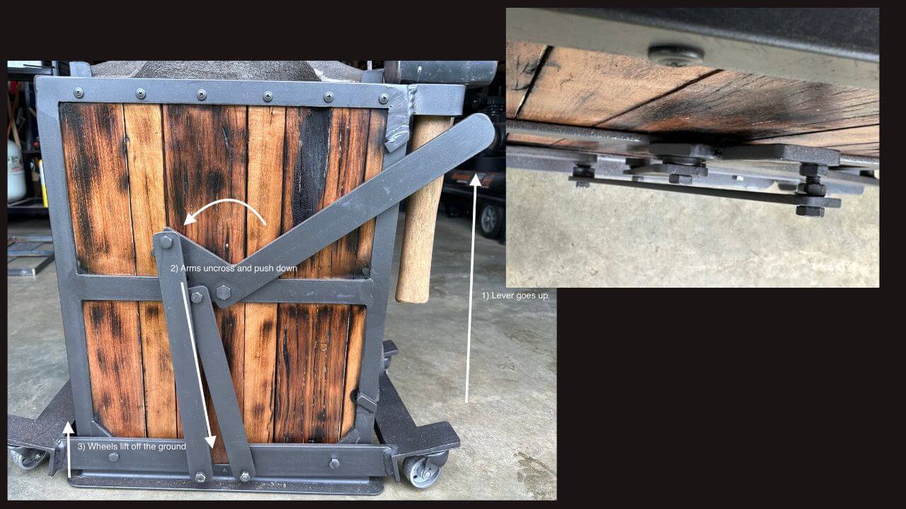
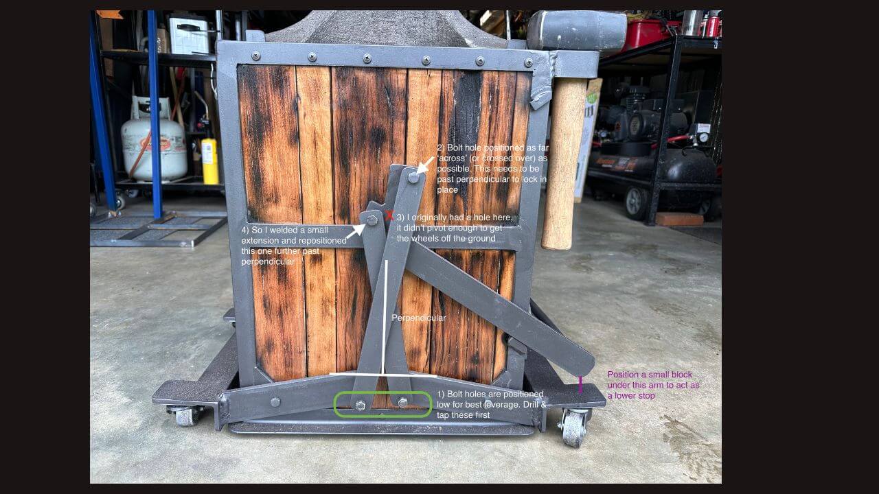
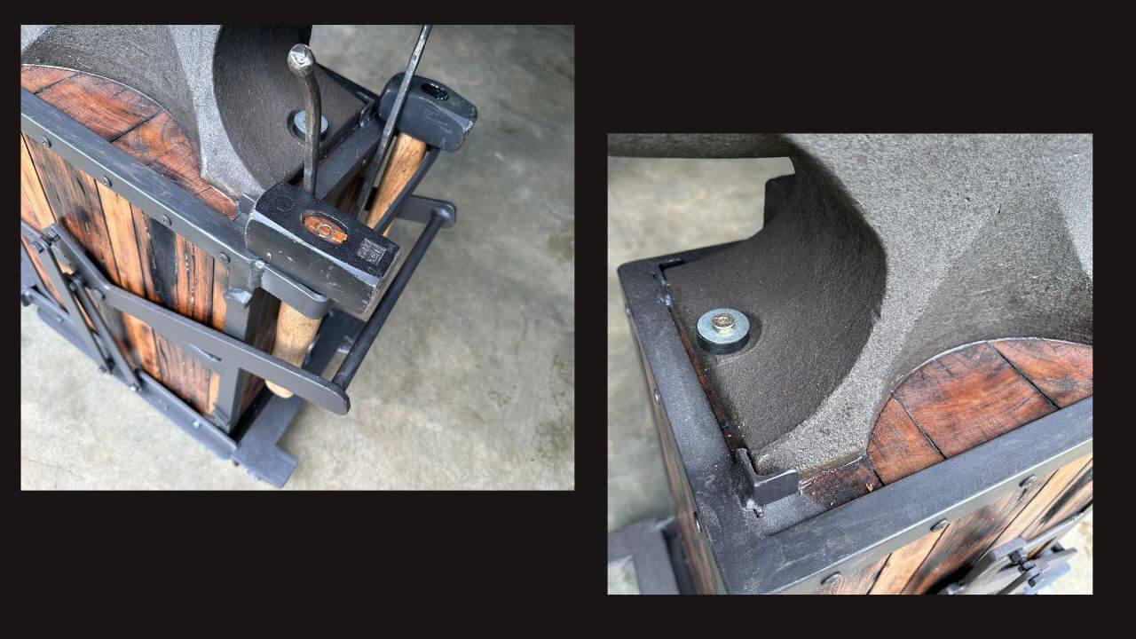
Here's where the eldritch magic occurs, and a little trial & error bears fruit. (Note the diagrams here side by side if easier to see how it works)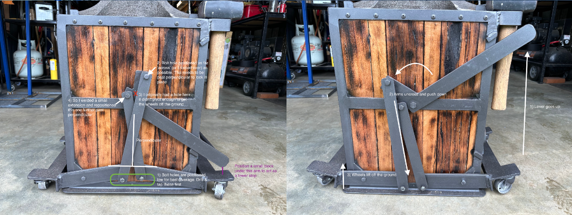
I started with the main pivot arm to its lowest position, with a small block underneath to act as a lower stop (until I could weld a stop tab in place), this just gave me a starting point with enough room to grip the handle.
Starting with the M6 bolt holes on the wheel arms first, these are positioned low for best leverage.
Next I drilled & tapped the top right/longest armature, positioning it as far off the (imaginary) perpendicular line and as 'crossed over' as possible.
Next I drilled & tapped the bottom left/shortest armature hole, positioning is again as far off the perpendicular as possible and lower so it doesn't interfere with the long armature.
(Originally, this hole wasn't far enough off perpendicular, so I welded a small extension on the main pivot arm to get it out further - messed up my hockey stick shape, but worked a treat)
Two appropriate length arms were then cut and plain M6 holes drilled to match the threaded ones just created. Washers and different bolt lengths were used to clearance these two armatures. The longer one just has to be outboard far enough for the short arm to pass under and through without catching.
Rinse and repeat for the other side and voila! One self locking up and over mechanism. Keeping the stand on blocks with wheels down and main arm down seems to offer a fixture jig of sorts. I'm positive my armatures and bolt holes on each side don't match identically, but tapping first, and sizing the armatures to these hole positions on each side seems to work - there's enough tolerance across the whole shootin' match that a few millimetres out here and there hasn't bound it up at all.
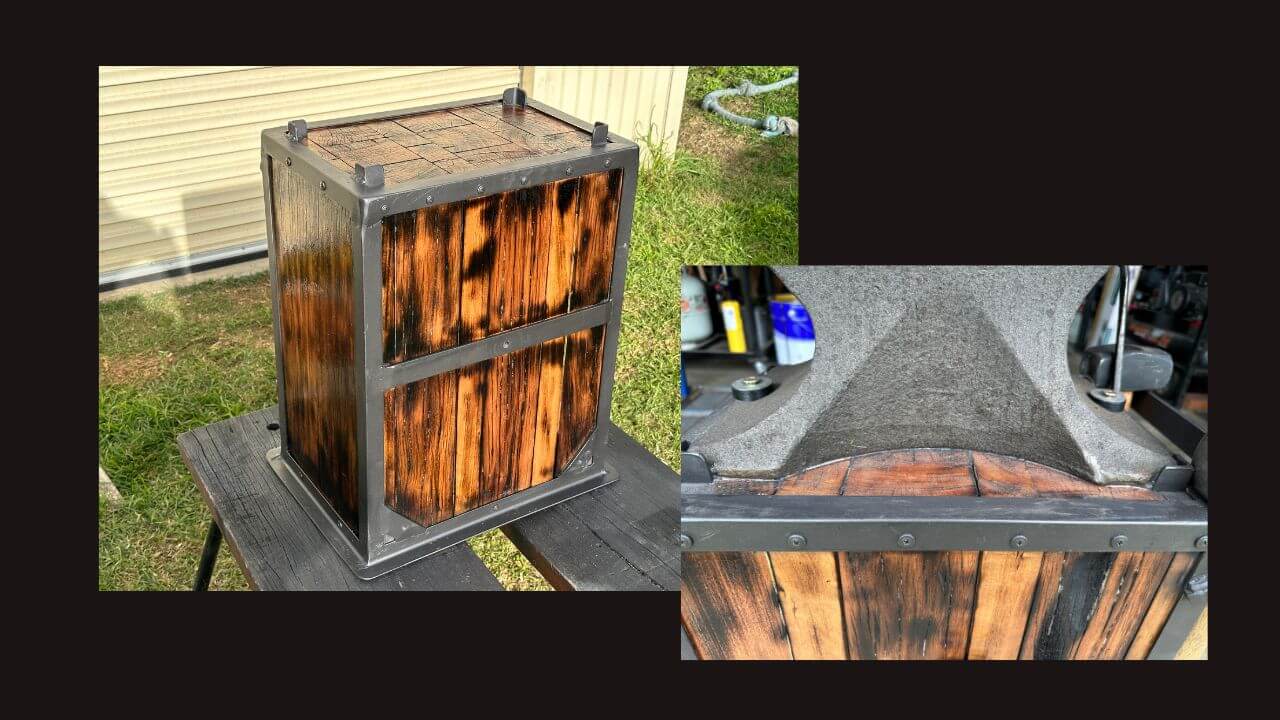
With the main mischief managed, finishing touches included some angle offcut tabs to centrally position the anvil and stop it walking. Some thread lock on the mechanism bolts to stop THEM walking. Stop tabs for the main arm (just on one side). Some light shou sugi ban japanese wood burning mostly to hide my weld scorches but also to bring out the wood grain… and a coat of marine varnish & gal paint to make it pretty.
Attaching the anvil, there's a generous bed of silicone under it, and some thick plastic/nylon washers between anvil and the 100mm coach bolts holding it down - all to affix the wondrous thing and help it stop ringing so much. The neighbours are yet to thank me, and we’ll see how she runs; we can always clad in lead, add a hefty magnet or wrap in chains if the bell continues to toll.
So, with my cloak of quiet humility now in tatters, Bjorn, thank you for the opportunity to share this. Likewise an enormous and heartfelt thank you for making such tools available to us in the land of Oz. It’s so very appreciated. To the fellow makers and mentalists alike out there, may you find inspiration here and pass the creativity on.
Here is the parts list, should you want to make your own.
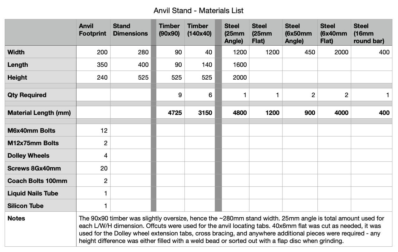
Steve
Northern NSW, Australia
****
Thank you, Steve. That is one cool anvil stand!
Why not give Steve a follow on Insta: LINK
Recent Posts
-

The Etch Test: Ferric vs Hydrochloric vs Gator Piss
The Etch Test: Three Very Different Looks From One Steel One of the great things about knife making …3rd Jan 2026 -

Why Bed The Tang In Epoxy - Then Knock it OFF Again.
What is "Bedding the tang"? Bedding the tang means gluing a stick-tang blade into the handle block i …21st Mar 2025 -

Marble Leather - How to Dip Dye Veg Tanned Leather
This was my first experiment with hydrodipping or dip dying leather, and it came out pretty cool! I …14th Mar 2025